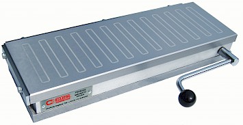
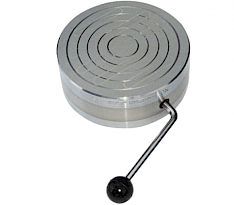
Let your Business Work Smart with Magnetic Chucks

If used correctly our magnetic chucks can be used to drive time, quality and money-saving efficiencies into your business. Below are some useful workholding tips that can help you  'Work Smart with Magnetic Chucks'.

Holding irregularshaped workpieces

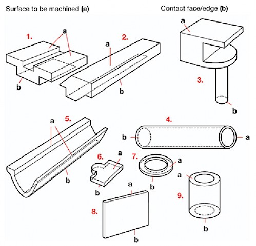
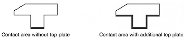
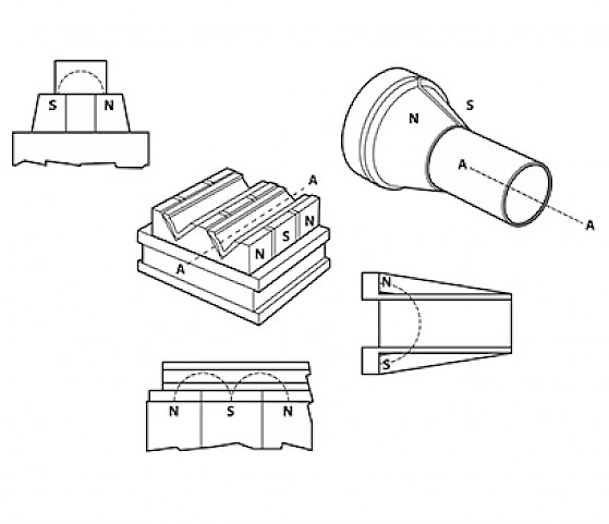
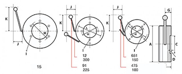
Most workpieces that are difficult to hold have the common problem of small surface area in contact with the chuck top plate. Each of the workpieces below can be held magnetically using the techniques as shown beside the image. Simple jigs made from mild steel and non-magnetic material make the holding of such workpieces easy and give positive location time after time.

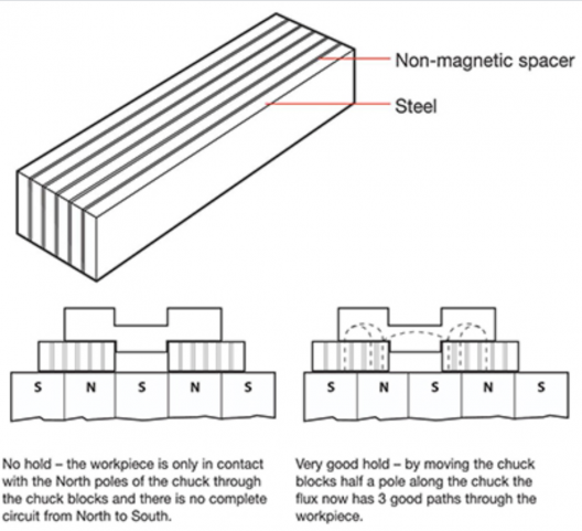
For toolroom and ‘one-off’ applications, the simplest of these jigs are Eclipse Chuck blocks, of laminated mild steel and resin construction. They can be machined with Vee’s etc. if necessary. Chuck blocks extend the lines of magnetism from the chuck’s North and South poles. Correct positioning on the chuck is therefore important to obtain the best workholding.

For repetitive or production work an additional top plate can be purchased and profiled to suit the workpiece. In this case, the surface area is increased considerably and the pull is increased by 250%.

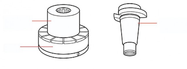
For deeper workpieces a simple jig is made from mild steel and a non-magnetic material. This makes their holding and positioning simple giving accurate location time after time. For small components, the effective contact area can be increased by multiple loading and packing around the sides and ends to give additional support. For one off machining of small, thin components a Fine Pole Chuck should be used. The component being placed across a brass lamination to achieve maximum hold.

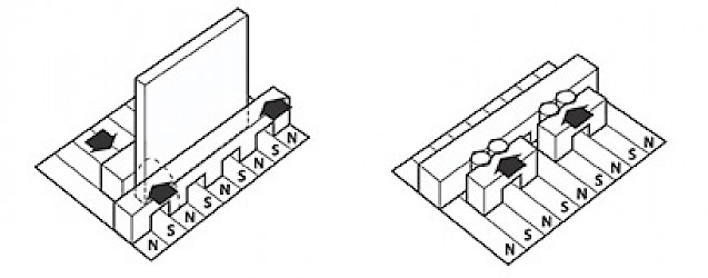
For flat of tall thin parts, a magnetic vice effect can be easily achieved with one jaw sitting only on the North poles and the other on the South. When a ferrous workpiece is positioned between the jaws the flux has a complete circuit back to the chuck and the workpiece is held without distortion, between the jaws. Alternatively, an Eclipse Magnetic Vice (E927) can be used in conjunction with any chuck or on its own.

Radial Pole - Special Pole Extension

Such units can be designed and supplied to suit your workpiece. Please contact our Sales Office for details.

Milling on AX, mechanically switched, magnetic chucks

The use of magnetic workholding in milling or machining centre operations can give considerable savings in:

  • (a) Jig and fixture cost
  • (b) Changeover allowances
  • (c) Load/unload times

It is recommended that the machining rates for each job are assessed and gradually built up to the optimum until sufficient data is achieved about materials, contact areas, workpiece thickness etc. To ensure maximum rigidity of the workpiece it is recommended that extra packaging/location pieces are used when the full chuck area is not being utilized.

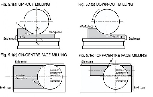
The mechanical forces to be resisted in milling are generally very much greater than in grinding, and the cutting action may be of an intermittent nature as each cutting edge strikes the workpieces. Furthermore, the direction of the forces varies from instant-to-instant during machine operations.

The purpose of a chuck is to hold work down. Resistance to sideways movement is approximately five times less than the downward pull and it is therefore important to use the side and end stops. Suitable blocks positioned between the side and end stops and the workpiece should be used to ensure the workpiece is over North and South pole.

Climb milling is advised in preference to orthodox milling. During vertical milling, the position of the table should be adjusted to control the directions of the mechanical forces so that the workpiece is pressed against the stops and not driven away from them. The centre of the milling cutter should move along the centre line of the workpiece whenever possible.

Machining Forces

  • Up-cut Milling - The cutter tries to pull the work up and push it along the chuck. The machining force is F tangential to the cutter, as shown in Fig. 5.1 (a). Its horizontal component FH is resisted by the end stop to the left, and the friction between the workpiece and chuck face. The vertical component Fv is resisted by the downward pull of the chuck. Fig. 5.1 (a) demonstrates two very important points. The duty of the chuck is to hold the work down. The duty of the end stop to resist sliding and for this reason an end-stop should always be used.
  • Down-cut Milling (or climb milling) - The machining force F is downwards towards the chuck and to the bottom right-hand corner of the workpiece, so the end-stop is placed at the end where the cut starts, Fig. 5.1 (b) As the cut proceeds, the machining force helps to hold the workpiece down on to the chuckface, and this means the heavier cuts can be taken than in up-cut milling. Down-cut milling is always recommended, therefore, provided the machine has been designed for this type of work.
  • Face Milling - For on-centre face milling, Fig. 5.1 (c), the action of the cutter tends to push the work up to the left-hand end and to the side of the chuck, because the centre of the cutter is over the centre of the workpiece. This condition cannot always be met, however, and it is sometimes necessary to position the workpiece off-centre in relation to the cutter. For off-centre milling of this kind, Fig. 5.1 (d), the workpiece is still pushed to the same side but towards the end-stop on the right.

It is, therefore, worthwhile to make a quick check before the feed is engaged to ensure that the workpiece, end-stop, side-stop, packings and thrust blocks are in the correct position to suit the particular cutting conditions. For heavy milling and awkward shapes, Eclipse recommends the use of their ‘Power Matrix’ Square Pole Chucks. 

Installing permanent magnet chucks

All Eclipse chucks have their top plates and base plates accurately ground flat and parallel before despatch, and are ready for immediate use.

However, careful checking is recommended before the chucks are installed on machines as there is always the possibility of damage in transit, unpacking or subsequent handling.

Installing chucks on machines: the vitally important requirements for high-precision machining apply to the installation of magnetic chucks of all types and not only those for high-precision work. The normal installation procedure is as follows:

  • Check the machine table for possible damage. It must be perfectly flat before the chuck is mounted on it. Ensure that the base plate of the chuck is truly flat. Remove any blemishes that may have occurred in transport or handling, with a flat, smooth stone.
  • Remove any flash on the top or base plate by light stoning. Scoring marks and other damage should be removed by re-grinding, preferably on the machine where the chuck is to be installed. Any distortion should be eliminated by grinding, using the procedure given below.
  • Absolute cleanliness is essential. In particular, there must be a complete absence of solid dirt particles between the machine table and the chuck base plate.
  • The chuck can now be fitted to the table and fastened down. Ensure that the chuck top plate is flat and parallel to the base plate. When installed on a grinding machine, the top plate should, as a final precaution, always be ground on that particular machine. Instead of removing circular chucks from lathes for grinding, they may be re-surfaced by turning, using the lightest cut and the finest feed practicable, followed by light stoning.
  • Regrinding: never be afraid to re-grind a top plate because it will reduce the thickness. The top plates of Eclipse chucks are thick enough to cope with many years of re-grinding before renewal is necessary. The most suitable grinding wheel for the operation is a medium-hard type with open grit grading. Deviations from the desired precision are generally caused by insufficient care in installation and maintenance. The control handle must be OFF when re-grinding.
  • Rectifying distortion (if damage has been suffered) - Take two parallel steel bars, each about twice as wide as a top plate insert. Place them over two inserts about a quarter of the length from each end of the chuck. Turn the control handle ON, to hold the parallel bars. Turn the chuck over, with the parallel bars on the machine table, and lightly grind the base. After rectification of the base, the top plate should be ground flat and parallel with it, preferably on the machine where the chuck is to be used.
  • Mounting chucks in multiple - For multiple mounting, chucks can be assembled on a common base plate which is, in turn, mounted on the machine table. AX 300mm (12") and 250mm (10") wide chucks have a cap screw in each corner which, for multiple mounting, should be removed and replaced with longer ones. The base plate is tapped and will require opening out to a clearance hole. Heavy-duty chucks AX1018 and AX1218 are available either for independent mounting or multiple mounting, in the latter case without projection of the base plate for clamps, and with a counterbored hole for a cap screw in each corner.
  • Rectangular chucks installed vertically - Eclipse rectangular chucks can be mounted on edge. A large angle plate may be used as a mounting, or alternatively, any device convenient to the user and sufficiently strong mechanically. Precautions should be taken to prevent the edges of the top plate and base plate from touching ferrous matter simultaneously, as that would short-circuit the magnetic flux and reduce the gripping potential. The introduction of a non-magnetic spacer between chuck and table will prevent short-circuiting. The non-magnetic spacer should be at least 3mm (1/8” thick). Suitable materials are brass and austenitic stainless steel.
  • Mounting smaller chucks on permanent magnet chucks - Sometimes it may be desired to mount other chucks and magnetic tools on chucks that are already installed on machines. The objects may be: To apply a finer pole spacing to small workpieces; To reduce the area to be re-ground when re-surfacing a top plate. To gain the advantages of the special shape of a magnetic veeblock or the particular directions of gripping of a magnetic vice. Such arrangements are normal. Small permanent magnet chucks, magnetic vee blocks, magnetic vices and similar tools should not be used on permanent-electro or on electromagnetic chucks.
  • Mounting circular chucks - When fitted on lathes, it is necessary to make a back-plate. The diagrams below and schedule over the page provide all the necessary dimensional information. It is particularly important not to insert into a base plate, screws so long that they project inside the chuck. Such projections can interfere with the moving magnet system and cause a seizure. If this happens, the chuck must be returned to the works for attention.

Permissible machining of permanent magnet chucks

The most important rule is that machining, whether drilling or otherwise, must NOT penetrate to the interior of any chuck. Drilling must not be so deep as to cause a projection inside a chuck. Penetration to the interior of a chuck could cause a loss of lubricant and admit coolant and dirt. Projections could interfere with the moving magnet system. Holes drilled should be at least 5mm (13/64") less in-depth than the thickness of the top plate or base plate. Holes should not be drilled in mild steel inserts or non-magnetic spacers, but in solid parts of the top plates.

Fine Pole chucks have a laminated top plate secured by tie-rods. These top plates can be drilled in any location OTHER than through these tie-rods. Tie-rod locations are easily visible from the chuck ends. Again, drilled holes should be at least 5mm (13/64") less in-depth than the thickness of the top plate.

Within these limitations, there is considerable freedom for simple machining in the top plate and base plate of any Eclipse chuck. For example, locating pegs and driving pegs can easily be fitted.

More complex machining may be contemplated to accommodate workpieces that cannot be held directly on the normal chuck surface. It is wise to give careful consideration of additional top plates and other magnetic fixtures to hold awkward shaped workpieces, before deciding on any but the simplest machining.

The machining of grooves, slots or recesses in top plates might be practicable and permissible, and ideal for the operation immediately ahead, but can spoil the chuck for other workpieces in the future. When an additional top plate is used, the basic chuck is unspoilt.

If machining other than the simplest kind seems unavoidable, the problem should be referred to our Technical Department. If machining of the chuck is then considered to be the best course, a check will be made for possible interference with assembly screws and dowel pins, and for any other possible adverse effects, and the customer advised accordingly.

Troubleshooting

The information below gives a simple cross-check to possible problems, if difficulties are still experienced please contact our technical department.

Problem Possible Cause

  • Installing chucks. Correct installation procedure has not been followed.
  • Chuck will not switch on/off FP/AX.
  • Surface has been damaged, preventing movement inside the chuck.
  • Workpiece will not hold on chuck.
  • Workpiece is not magnetic.
  • Material is not thick enough to absorb the available magnetism.
  • Workpiece is not positioned over a minimum of two poles (ie North & South).
  • Side and end stops are incorrectly positioned to counteract sliding along the chuck.
  • There are air gaps between the workpiece and chuck.
  • Workpiece will not hold on accessories jigs used with the chuck.
  • Accessories/jigs are positioned incorrectly on the chuck
  • The accessory/jig is incorrectly made or designed so that flux is short circuited.

Action

  • Refer to correct installation procedure and correct any errors
  • Check for damage, if any found return for repair
  • Check magnetic properties of workpiece
  • Ensure the correct chuck is being used
  • Check correct position of the workpiece
  • Position side and end stops correctly
  • Check cleanliness of chuck & workpiece
  • Check surface finish of workpiece
  • Ensure there is no alternative magnetic path that bypasses the workpiece